10/14/2016
vu meter clock | first prototype
I recently found an old (1980s?) radio/tape player/record player unit sitting in the trash pile behind my apartment. I took it back to my apartment because I thought it would be a treasure trove of electronic and mechanical parts. In taking it apart I scored some motors, pulleys, gears, vintage buttons and bulbs, and a lot of electrical components (though some are usless due to their age). The most exciting components I salvaged were three of these VU meters.

I've been wanting to learn how to use Solidworks' built in sheet metal design tools for a while now as well as learn how to work with sheet metal. I had three of these meters, I figured they'd be perfect to build a clock out of (not that it's a new idea), so I decided to kill two birds with one stone.
I modeled up the meter itself and then just tried various shapes in Solidworks until I was happy with the shape of the enclosure. I settled on this triangular sort of look with the front face sloping backwards a bit, which I thought would look neat as well as make the clock visible when placed on a desk.

I struggled a bit figuring out how I would have all of the bolts go in from the outside and still be able to hold the nut from the inside of the case. I thought for a while about how I would not close up the case while simultaneously preventing me from clamping onto the nuts. I honestly was about to just leave a hole in the bottom until I found these press-in nuts on McMaster-Carr. These are pressed into a hole which makes the teeth on them grab into the surrounding metal. Perfect solution to my problem. I could have also used sheet metal screws, but I was shying away from them.
Here's the water jet cutting out the pieces. I had a bit of a struggle getting the piece of metal to stay flat. I think in the future I'll try and use a sacrificial piece of plywood or MDF to keep the thin metal flat in the bed. If the metal bows up or down while cutting (which can happen easily as the water pressure usually pushes back up as the jet shoots into the water) a slightly distorted pattern is cut.
After the pieces were cut I pressed all of the nuts into the sheet metal. When bending the metal on the brake, I ran into some problems turning the digital representation (which has perfect bends) into a physical one. The main problem was that the main piece bent back onto itself, which made it impossible to make the last bend without the piece running into the brake. Another problem I had was the brake running into the press nuts, which made it hard to get an even bend.
I ended up kind of completing the final bend by hand, just to say I sort of finished it. But the result wasn't pretty.

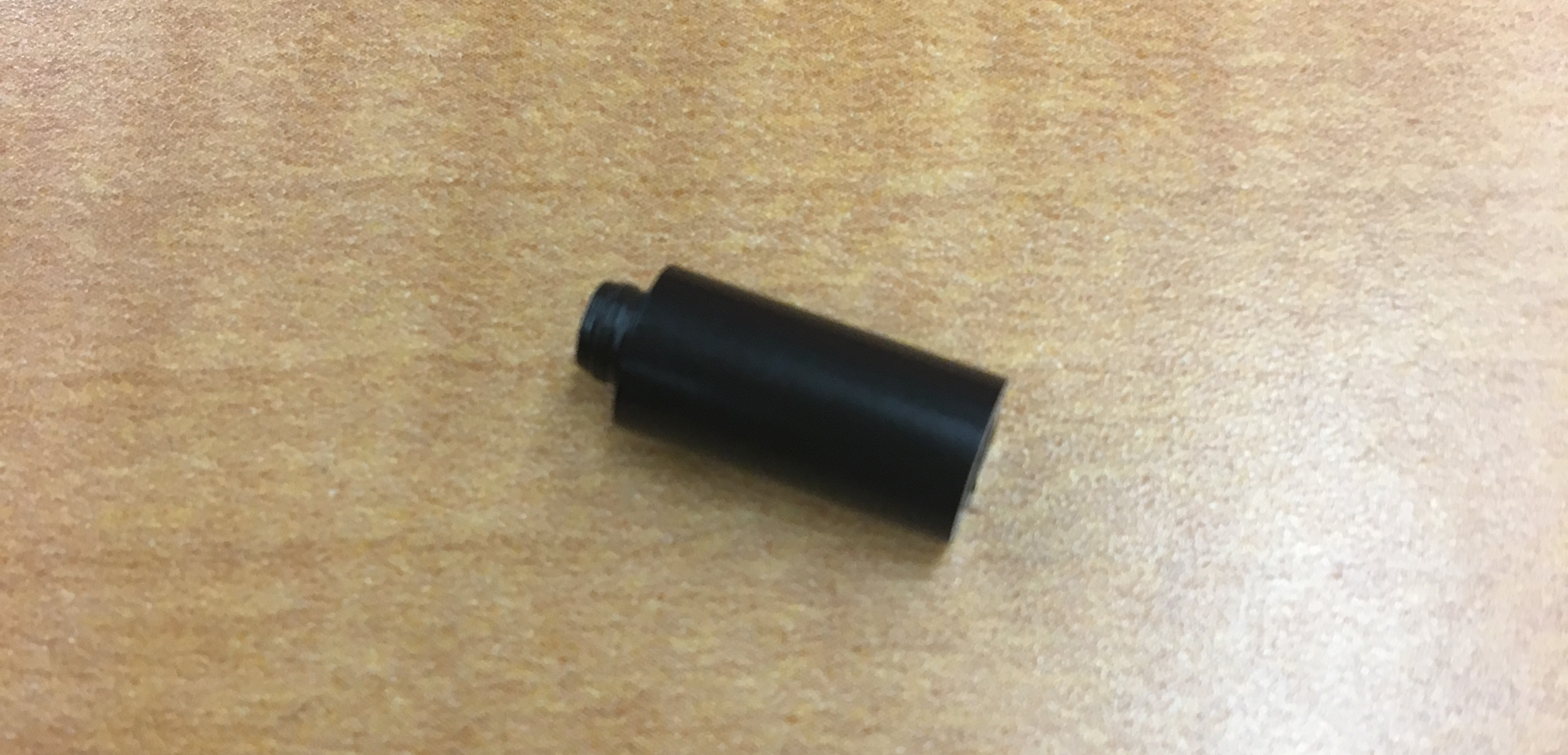
To hold the meters in I was planning on using some spacers but couldn't find any of the right length. They needed to be as deep as the meters so that the bar could go across the back of the meters but still be attached to the front. You can see this in the photos of the 3D model above. I couldn't find any spacers that were the correct length, so I thought I'd try making some on the lathe. I bought some delrin rod and cut some small spacers. They turned out fine, the flange is due to the parting tool. I was going to clean these up but I'm going to redesign the enclosue so that it doesn't require the spacers, so there's no reason to now.

I do want to install some LEDs inside the case to backlight the meters, here's what that might look like.

The last issue I found with this design was that the clamping plate that I desnged to hold the meters in blocks almost all of the backlight from reaching the meter, so I'll have to redesign the clamp so that it grabs at a different location. Not much force is needed, the clear cover on the front of the meter fits pretty snuggly in the holes of the enclosure, so the clamp is just for extra security.